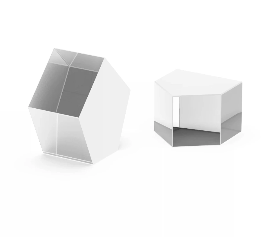
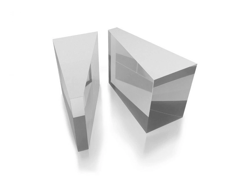
Rhomboid
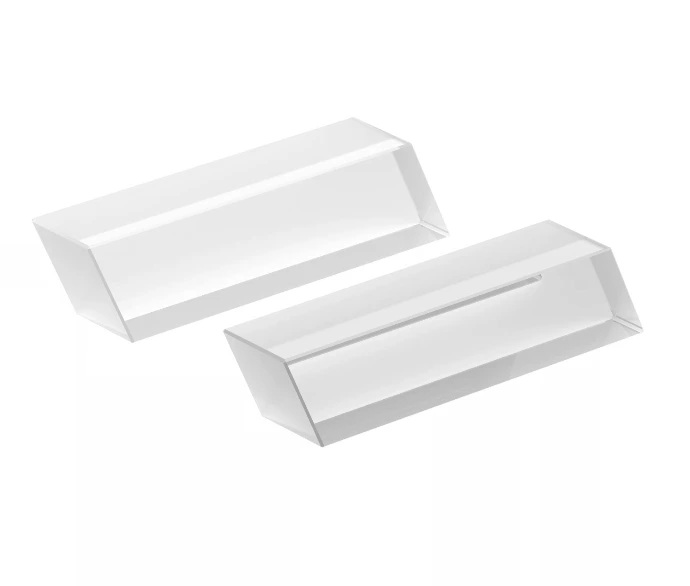
A prism with a parallelogram cross-section that laterally displaces a beam in one direction without changing the beam's propagation direction or inverting the image. The standard element for displacing an optical axis in imaging systems, stereoscopic viewers, and laser beam routing where beam displacement without angular deviation is required.
Cross-section
Parallelogram
Beam deviation
0° (parallel displaced)
Image effect
No inversion or reversal
Reflections
2 TIR
Overview
- Parallelogram cross-section with two parallel faces and two angled faces — the angled faces provide two total internal reflections
- Light enters one parallel face, undergoes two TIR reflections at the angled faces, and exits the opposite parallel face — parallel to the entry beam but laterally offset
- The lateral displacement is determined by the prism's width and the angle of the angled faces — typically 45°
- Unlike a right angle prism, a rhomboid prism does not invert the image — the output image is identical in orientation to the input
- Displacement is in one axis only — the output beam travels in the same direction as the input but is shifted perpendicular to it
- Two reflections provide zero net image inversion — the even number of TIR reflections preserves image handedness
Key Features
Zero-deviation beam displacement
The input and output beams are parallel — the output direction is identical to the input direction, only displaced laterally by a fixed distance. This allows beam axis displacement without any angular deviation, meaning downstream optics need no realignment when the rhomboid is inserted into a beam path.
Image-preserving optic
Two TIR reflections preserve image handedness — the output image is identical in orientation to the input. This makes rhomboid prisms ideal for imaging applications where the optical axis must be displaced (for example, to route a beam around an obstacle) without distorting or inverting the image.
Stereoscopic applications
Rhomboid prisms are used in stereoscopic imaging systems to adjust the inter-lens spacing — displacing one optical channel laterally relative to the other to match different stereo base geometries while maintaining identical image orientation in both channels.
Lossless TIR
Both reflecting surfaces operate by TIR — no metallic or dielectric reflective coatings required. This provides essentially lossless reflection at both surfaces, making the rhomboid prism more light-efficient than any mirror-based beam displacement system for visible and NIR wavelengths.
Design and Construction
Geometry & specifications
Geometry
- Entry and exit faces: parallel flat faces; perpendicular to the optical axis
- TIR faces: angled at 45° to the parallel faces — one at each end
- Displacement distance: determined by prism width (W) and face angle (α): d = W × cos(α)
Tolerances
- Angle accuracy: ±1 arcmin standard; ±30 arcsec precision
- Parallelism of entry/exit faces: <30 arcsec — controls output beam angular deviation
- Surface flatness: λ/4 standard; λ/8 precision
- Surface quality: 60-40 standard; 20-10 laser grade
Coating options
TIR faces
- Uncoated — TIR provides essentially 100% reflectance for visible and NIR in glass
- Protected Al — for configurations where TIR angle is marginal
Entry/exit faces
- BBAR AR — reduces ~4% per-surface reflection loss
- V-coat — for single laser wavelength applications
- Uncoated — for low-power broadband applications
Optical Materials
Standard glass
Visible & NIR
- N-BK7 — standard substrate; wide availability; visible through NIR
- N-SF11 — compact designs; shorter prism at same displacement due to higher index
UV-grade
- UV Fused Silica — UV laser beam displacement and UV imaging systems
Specialty
IR & rugged
- Sapphire — rugged environments; UV through 5.5 µm
- ZnSe, Germanium — IR beam displacement in MWIR/LWIR systems
Wavelength Options
UV
- 240–400 nm
- UVFS
- UV-AR faces
Visible
- 400–700 nm
- N-BK7
- BBAR or uncoated
NIR
- 700–2000 nm
- BK7 / UVFS
- NIR BBAR
LWIR
- 2–12 µm
- Ge / ZnSe
- BBAR + DLC
Applications
Laser Systems
Beam axis displacement
Displaces a laser beam laterally without changing its propagation direction — used to route beams around mechanical obstacles, offset the beam axis to align with a downstream optic, or create a parallel beam at a different height without any angular deviation.
Imaging
Optical axis displacement
In imaging systems, displaces the optical axis to route the beam around obstacles or adjust the field of view position without changing the image orientation or requiring realignment of the lens train. Used in endoscope design and surveillance camera optics.
3D Vision
Stereoscopic viewers
Used in stereoscopic camera adapters and 3D microscopes to adjust the stereo base — displacing one image channel relative to the other to control the stereo convergence angle and interpupillary distance alignment without inverting either image channel.
Sensing
Differential sensing
Used in balanced detector and differential sensing configurations to create two spatially separated, co-parallel beams from a single input — enabling simultaneous measurement at two positions without a beamsplitter's 50% transmission penalty.
Metrology
Alignment & collimation
Used in precision optical alignment systems to offset the beam axis to a reference position — the zero angular deviation property ensures that only position changes, not direction, enabling position-only adjustment of the beam reference.
Defense
Periscope design
Two rhomboid prisms in series (displacing vertically and then back to the original height but at a different lateral position) form the core of periscope optical paths — displacing the observation axis over a barrier while maintaining image orientation and direction.
Why choose Rhomboid Prisms
Zero angular deviation
The only standard prism that displaces a beam laterally with absolutely no change in propagation direction — ideal for optical axis relocation without realignment of downstream optics.
Image-preserving
Two TIR reflections preserve image orientation — the displaced beam carries an identical, non-inverted image compared to the input, unlike right angle prisms that invert.
Lossless TIR
Both reflections are TIR — no metallic coating loss, more efficient than any mirror-based beam displacement system at visible and NIR wavelengths.
Compact displacement
Provides beam displacement in a single, compact, solid glass element — replacing a two-mirror periscope arrangement with no alignment-sensitive mirror mounts.
Frequently asked questions
Here are some common questions about Rhomboid.
A right angle prism deflects a beam by 90° and inverts the image in one axis. A rhomboid prism displaces the beam laterally with zero angular deviation and no image inversion. For applications requiring beam displacement without angular deviation (e.g. routing a beam around an obstacle to a co-parallel path), the rhomboid is the correct choice. For applications requiring 90° beam turning, the right angle prism is used.
Yes. The lateral displacement is determined by the prism's width and the face angle: for 45° face angles, displacement = prism width × cos(45°) ≈ 0.707 × width. By specifying the prism width, the displacement can be set to any required value. Custom rhomboid prisms with specific displacement distances and aperture sizes are routinely produced — particularly for stereo camera adapter and laser beam routing applications.